A Tiny Solar Tracking Weather Station with ESP32
It is easy to make something that works. But usually things that work tend to break pretty quickly. The main goal of this project is to see how an unusually complex system built out of sketchy cheap electronics and 3d printed bits holds up against the sheer brutality of the elements and relentless destruction of time.
Check here to see if it still works! https://weather.stcatsiow.com/
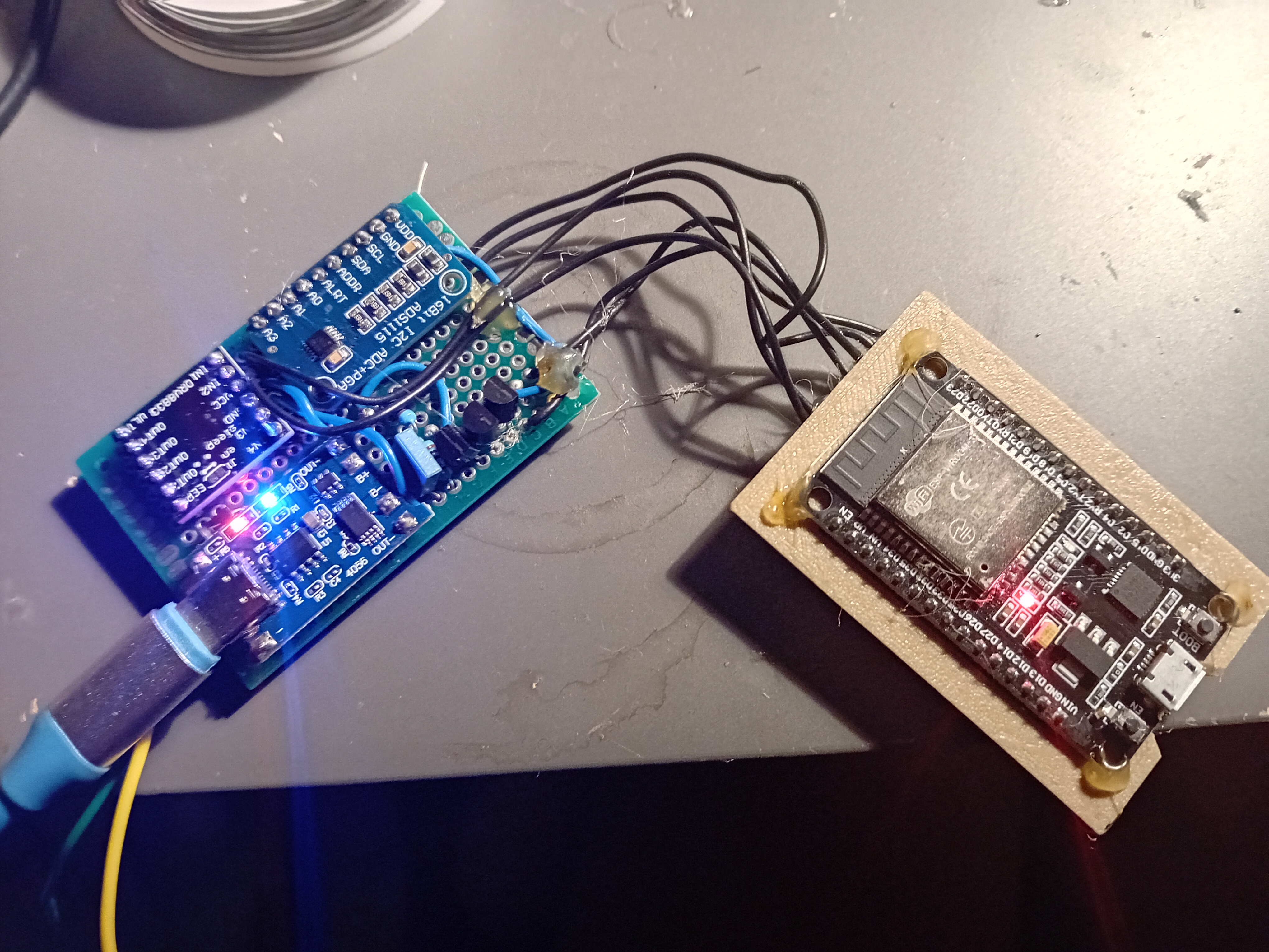
Construction of the electronics was relatively simple. I ordered all the bits I wanted and put them together, to find that shockingly it all seems to work just fine without any horrendous unexpected issues. "xc\z." - cat typed this so i gotta leave it. Anyway, I didn't make any circuit diagrams cause that's boring and its way easier to just make it up as I go along. I do, however remember what all the components do.
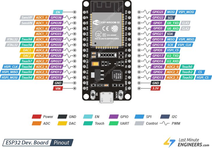
Esp32 is the brains of the project. Code goes in through the USB port and then it does whatever I tell it to. It can even connect to WIFI which will be really useful for this project.
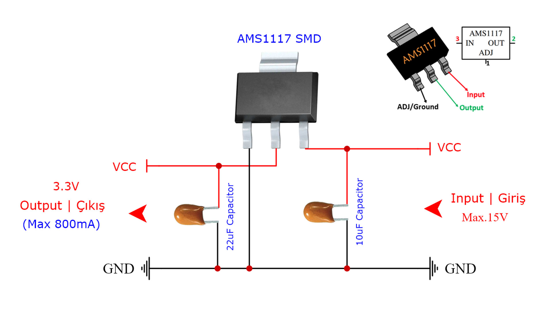
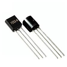
I inevitably had to amputate the AMS1117 3.3 volt regulator and replace it with the much better HT7333 because the massive quiescent current was draining the battery. Also AMS1117 needs an input voltage at least 1.3 volts higher than the output, which is a problem because battery = 3.7 volts and esp32 = 3.3 volts. HT7333 only needs 0.2 or something ridiculously tiny so it's fine. Trouble is, I discovered that the output voltage of the HT7333 regulator drops if the current through it goes over its 0.25 amp limit. ESP32 at max operating power takes 0.6 ish amps. Therefore instead of bothering to search for a bigger regulator i simply whacked 3 in parallel to hopefully get 0.75 amps before the voltage drops. I know this is terrible practice due to thermal runaway and all that, but in practice it solves the problem perfectly, and HT7333 seems immune to overcurrent anyway.
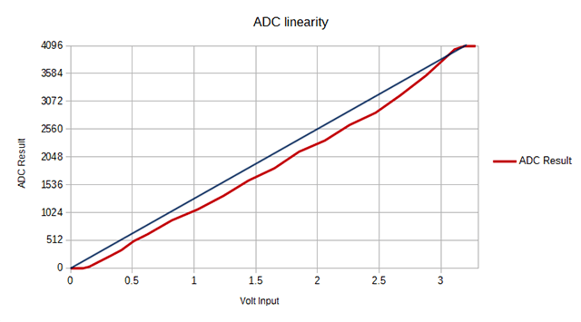
The ESP32 is required to measure the battery voltage and several analog sensors, but unfortunately its 2 inbuilt analog to digital converters (ADCs) are absolutely terrible.
To avoid all the second hand embarrassment and hours of optimising polynomial calibration curves, I grabbed one of these and soldered it in.
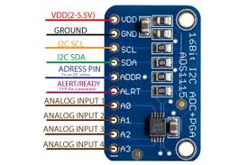
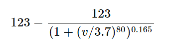
The ADS1115 is an ADC with much better accuracy and resolution, meaning we can read the battery voltage accurately within a few millivolts and calculate percentage charge using this formula:
The battery i decided to use was two large 500mah vape batteries soldered in parallel, creating a 1000mah 1s lipo.
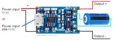
To avoid exploding the battery, we must use a charge controller, in this case a TP4056 because it is cheap and mainstream and does the job. It even has some cool features that stop the battery from shorting and stop it draining so empty that it causes damage. In this case the power input comes from the 6 volt solar panel and goes through a Schottky diode to prevent charge leaking backwards through the panel at night. I don't even know if this is possible with the tp4056 but its better safe then sorry. The idea is that 3.7v (empty battery voltage)+0.3v(TP4056 regulator minimum voltage drop) +o.3v(Schottky diode) = 4.3v which should be around the maximum power point for this 6v panel. Really I should be using a proper MPPT controller instead of pure guesswork and conspiracy theories but there isn't enough space on the board for any more bits and this works well enough for now.
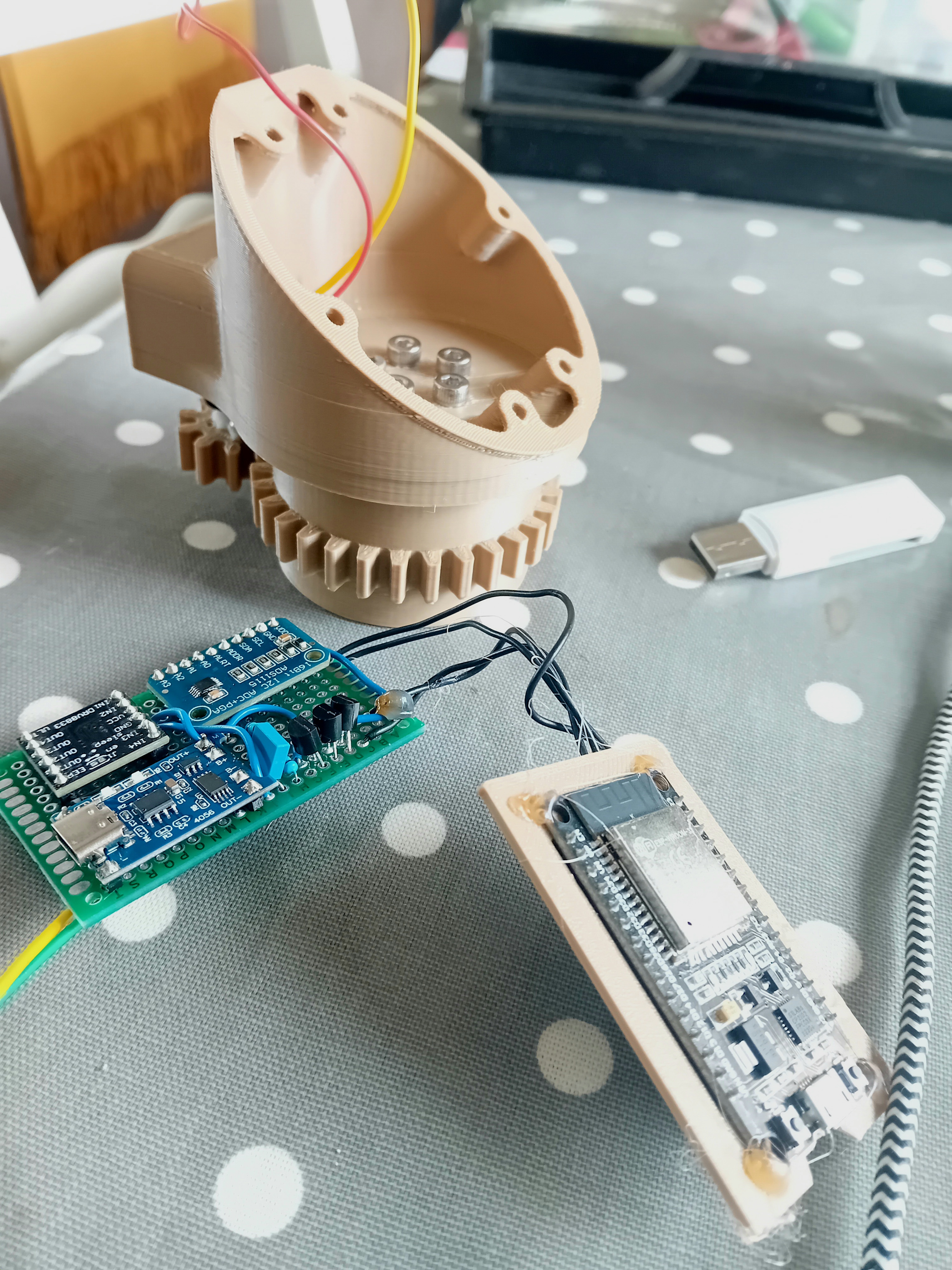
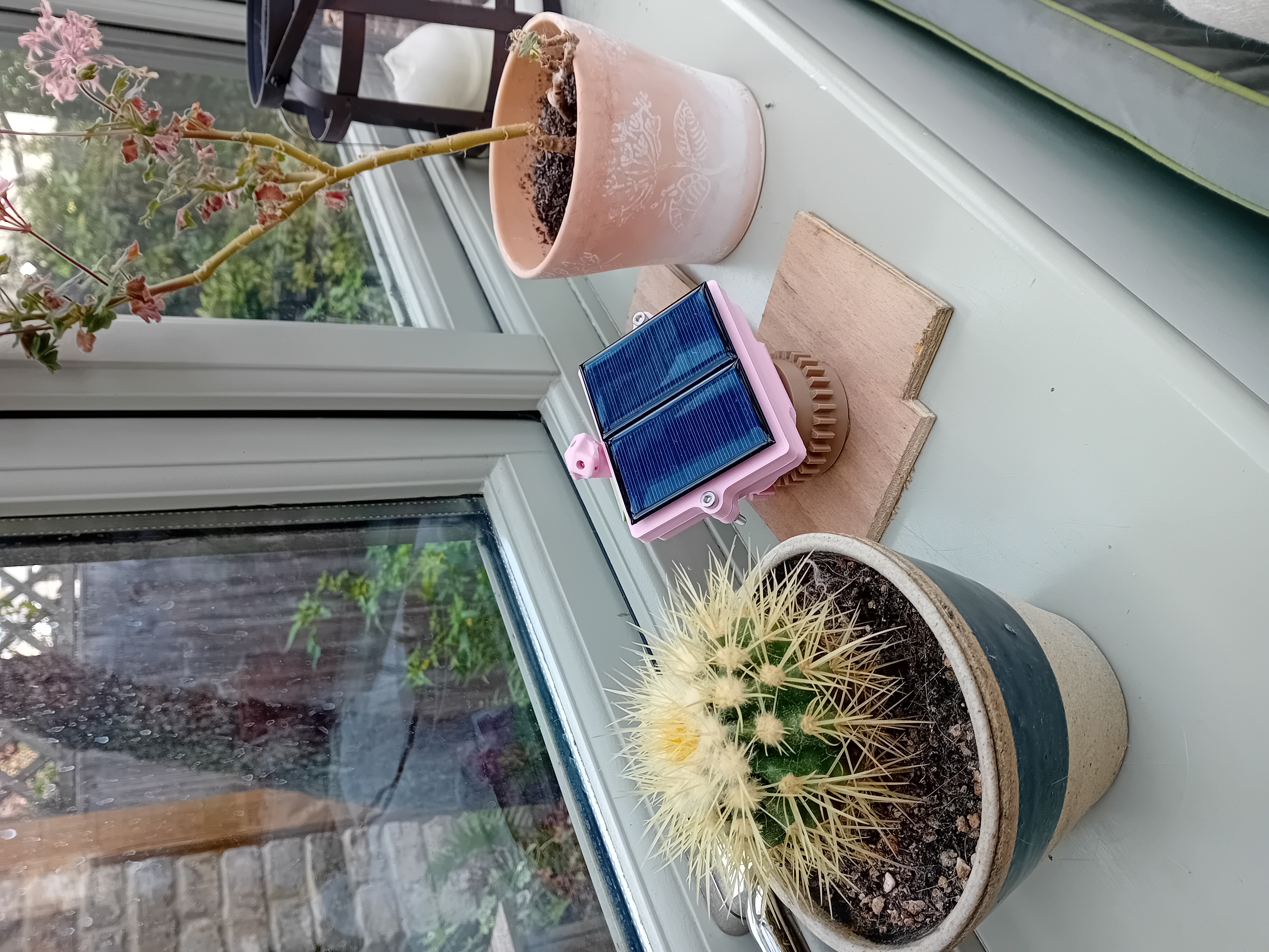
As you can see I already printed the body of the weather station long ago. It can use a tiny lobotomised servo motor at the back to turn the entire top section in relation to the bottom section. This means it can always be pointing towards the sun, without any need for bending and tangling cables. The problem, however, is obvious. There is absolutely no way that the electronics are ever going to fit inside. Time for a bunch more painful hours of Fusion 360 design and wasting hours forgetting that leaving Cura slicer open blocks all Arduino/ESP32 uploads!
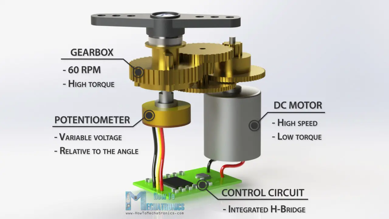
In case you were wondering, lobotomising a servo motor is as easy as removing the potentiometer and control circuit, and powering the motor directly. This means the motor becomes a normal geared motor and can spin around and around endlessly. Servos have really good torque because of their amazing gearbox, but in my servo there was a strange plastic cylinder sticking out of one of the gears which had to be snipped off to allow the servo to spin endlessly and give the desired unlimited range of motion. Unfortunately powering motors directly from the ESP32 will certainly fry the chip, and even kill the PC that you use to upload code! This means we need a motor control board with inbuilt back EMF protection.

For this low power application the tiny DRV8833 will do the job. It can control 2 motors in both directions, and the H-bridge also allows you to coast or quickly brake the motor. The motor is directly powered with unregulated battery voltage, which works fine and puts less current through the regulators. The DRV8833 can also be put to sleep when not in use, which saves a lot of power.
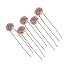
To know which way to turn, the device must know which way is the brightest. if there is more light on the left, it goes left. if there is more light on the right, it goes right. To do this I used 3 LDRs oriented at 60 degrees to each other and a bunch of code that works perfectly at least some of the time (cloudy days are really confusing for it which needs fixing). LDRs are an analog sensor so I used the 3 remaining inputs of the ADS1115 ADC.
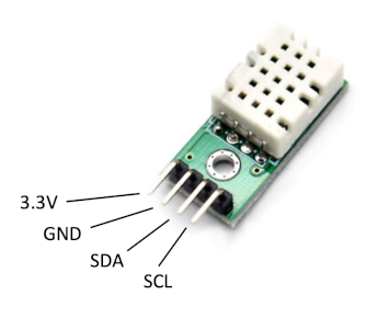
To measure temperature and humidity I decided to use the SHT C3 sensor. These Sensirion sensors are excellent and far superior to the DHT crap you see everywhere, and surprisingly the SHT C3 is actually pretty cheap. using the SHT and ADS1115 on the same I2C bus gave zero issues as they thankfully have a different I2c address.
I decided to power the SHT C3 and LDRs all with one ESP32 pin, as its 40ma limit far exceeds the power requirements of these sensors. This is good because it means the sensors can be turned off when not in use. Even though the power draw is small, 6 milliamps is enough to drain the battery within a week, so power must be saved wherever possible..
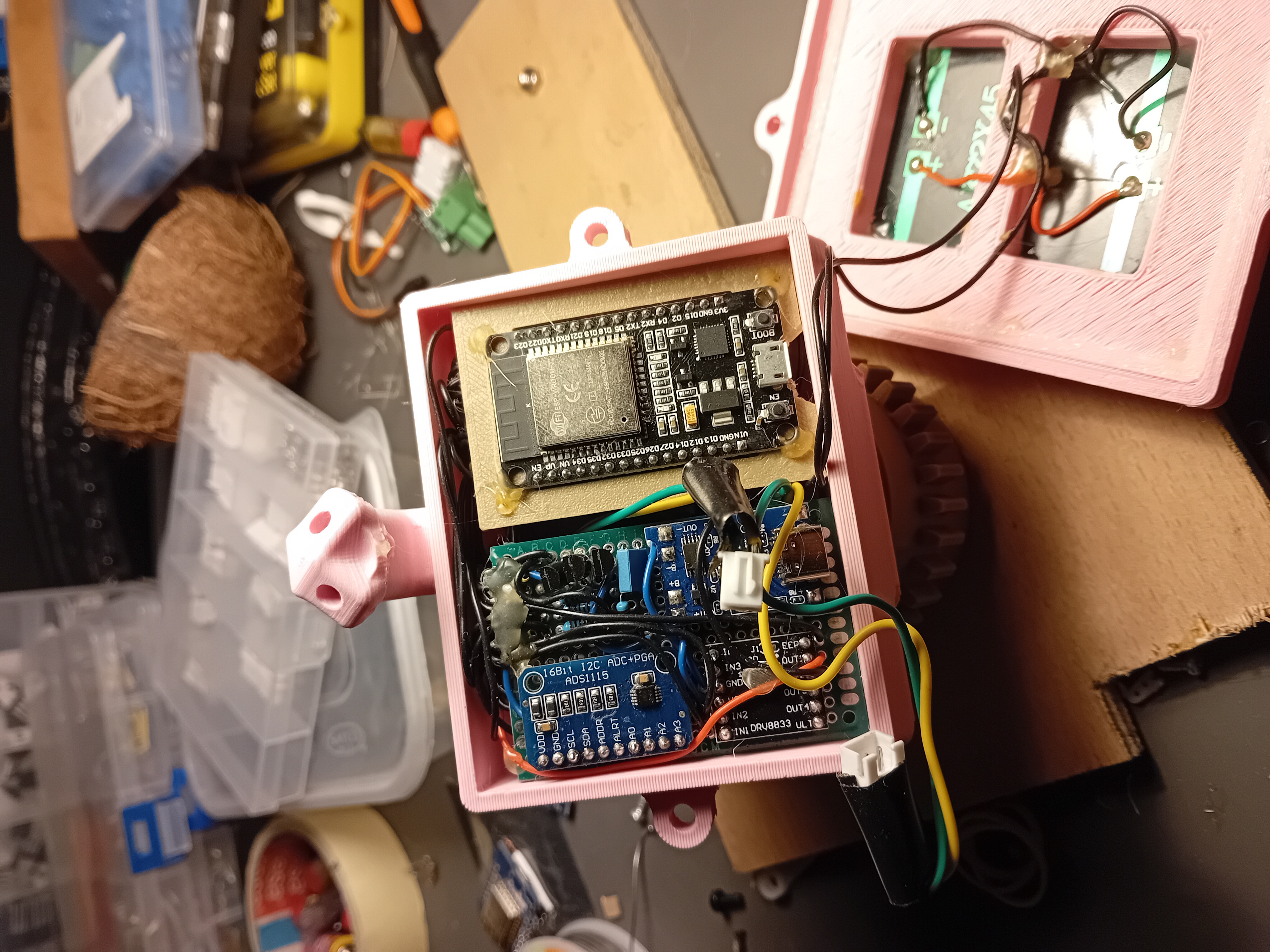
Finally I have a design that actually fits the electronics. It sure looks ugly but its not like I care at all at this point. I only decided to use 2 bolts to hold the lid on, because my patience is used up. The bizarre little tower at the back contains the LDRs. I am still trying to find a place to stick the googly eyes.
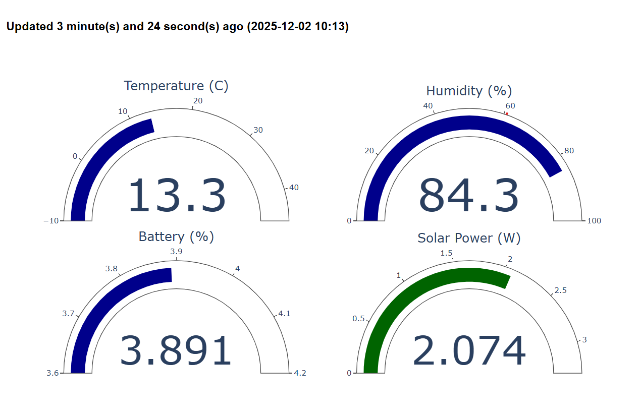
As you can see the solar tracking system works unexpectedly well. In reality it only adjusts itself every 10 minutes if necessary.
The website was constructed in python with great difficulty. In the end it turned out that Flask solves all problems. There are still some features that need updating, such as the battery voltage mislabelled as %.
Check here to see if it still works! https://weather.stcatsiow.com/
Final observations as the season draws to a close:
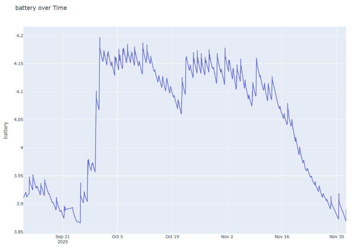
It has actually survived several months and has not broken down once!
Bigger solar panel is obviously needed for the winter, but it can enjoy the summer months with a full stomach. Next version will have a much larger panel and MPPT controller.
LDRs oxidise when they get wet, which is a huge problem because it is slowly going blind. The next version will have all LDRs completely protected behind glass.
I wasn't expecting my half hearted waterproofing to hold up very long but it is somehow bone dry inside after having a very rainy autumn and only 2 bolts holding it together. must be the dodgy 3d printed TPU seal actually doing its job!
It needs legs. I never bothered to make it any legs.